Software System
Robot Operating System
The team has elected to build most of its software using Robot Operating System (ROS), a modular framework for collaborate robotic software development. The modularity of ROS eases efforts to break the software system into manageable projects throughout the school year and then integrate them into the full system as they are completed. The collaborative aspect of ROS encourages many researchers and corporations to provide open source modules (called packages in ROS) which implement a variety of algorithms and device drivers. By taking advantage of this pre-existing software, the team saves significant development time and gains the ability to learn from the work of experts. The team has created a number of its own packages to operate its AUV. The most significant packages are Autonomy, Estimation, Navigation and Vision, as seen in Fig 16.
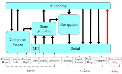
Fig 16. Software package stack.
The Autonomy package runs the mission by creating a sequence of desired states throughout the competition. The Estimation package continuously analyzes feedback to determine the vehicles current state. To travel throughout the course, the Navigation package resolves discrepancies between the desired and current states to create thruster commands. The Vision package handles the vehicle’s primary sensors, the forward-facing stereo camera system and the downward-facing monocular camera system.
A number of open source packages were used in conjunction with those created by the team, such as the imu_3dm_gx4 packages [1].
A number of smaller packages were also created to support those listed above. A serial interface package enables communication with the team’s custom electronics system and, by extension, the remaining sensors and actuators. A Teleoperation package was created for initial control testing and vehicle demonstration. The Description package provides a vehicle model which can be accessed by other software to determine the vehicles properties when making dynamic calculations.
Autonomy
The State Machine is the decision-making tool that allows the computer to control its behavior autonomously. SMACH is a package in ROS that provides these functions to be used in easier form [2]. In SMACH each state defines the actions or tasks to be performed. This allows Riptide to execute each task and make transitions smoothly, and it also allows team members to monitor the vehicle’s state. One of the classes in SMACH that was particularly useful was the SimpleActionState, which allows the state machine to access nodes through action files. This feature was necessary since the state machine manages and operates specific nodes accordingly.
Controls
The vehicle control stack is comprised of a thrust mapper and a thrust calibrator. These components begin with an acceleration vector, provided by the navigation stack, and ultimately activate the thrusters in any combination necessary to achieve said acceleration. The modular form of this system allows for control by either high-level mission planning software or direct user input, which has proven useful for testing purposes.
The thrust mapper solves the equations of motion for the vehicle using a non-linear solver called Ceres [7]. This determines what force each thruster must produce in order to yield the required acceleration. Success of the mapper relies heavily on the accuracy of the error calculated by the PID controllers as well as the mathematical representation of the vehicle as a physical body, provided by the model. The mapper succeeds when it finds a solution for the thrust required by each thruster within certain constraints, such as maximum thrust possible. If no solution exists, the mapper outputs an error which is then handled by the rest of the system as needed.
Using the forces provided by the thrust mapper, the thrust calibrator transmits the PWM signals activating the thrusters as required. The challenge in developing this component lied in finding which PWM signals actually yielded the desired thrust. Being the only component in the stack with a physical output, testing its real values required significantly more effort than the components with software outputs.
Navigation
The current state of the vehicle, determined from the Kalman filter, is used in conjunction with the desired state provided by the state machine and several PID controllers to ascertain required x, y, and z acceleration values. The PIDs are configured and outputs calculated by leveraging the Control Toolbox class in ROS [5]. The PID controllers are implemented separately for linear and angular accelerations, as shown in Fig 18, and for each axis in order to provide the most accurate PID parameters for each case. The PID parameters can be updated real time by using Dynamic Reconfigure [6]. The desired state can also be provided by a joystick from the surface in the case of tethered movement during the testing phase. This capability allows for easy tuning of the PID controllers and stabilization assessment.
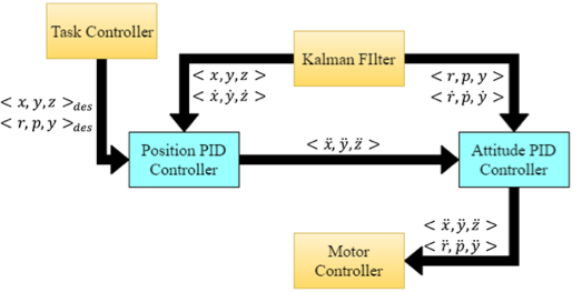
Fig 18. PID diagram
Estimation
The outputs from the two IMUs, mono visual odometry from the bottom-facing camera, absolute position estimates from the vision system, and depth measurements from the pressure sensor are inputted into an extended Kalman filter, specifically the EKF Localization node [3]. This filter then produces estimates for the absolute linear and angular positions and velocities of Riptide. For consistency between ROS nodes and simplicity in setting the desired states of Riptide, the world frame is utilized for all calculations. Since several sensors output in the body frame, for example the IMUs, transformations are necessary. This is completed using the tf package in ROS [4].
Vision
The Riptide Vision System revolves around the three cameras onboard the vehicle. Two of the three are mounted in the front side-by-side and provide a depth map via OpenCV stereo camera algorithms. Additionally, each camera outputs both a color and monocular rectified image for general color and contour matching algorithms. As a team in its first year competing at AUVSI, algorithm design was kept relatively simple. Each algorithm is stored in a general purpose library which can be called on with only an image as an argument. Having simple function contracts allows those working on mission design logic to utilize the vision library to its full effectiveness by not having to understand every detail of the vision system, only needing to understand the concept of passing in an image, and getting a heading or distance in return.
This is the team’s first attempt at a computer vision system, as such, a lot was learned very quickly. This includes the distortion of colors based on location, time, and depth of submersion. Additionally, there are a variety of ways to go about doing each task with no clear winner. Up to four versions for each algorithm were developed, each shined in certain circumstances and flopped in others. For example, the algorithm which determines the direction of the orange marker went through three iterations, one which detected the rectangular shape and drew conclusions about the heading via the corners, one which found the middle point of the object and then the middle point of the top half and bottom half, and the heading from those two points. Lastly, the winner, operates by taking the threshold of the color orange, yielding a black and white image, with white points being where orange is in the original, and an average line is calculated based on those points. The theory is that the distribution of points will always form a best fit line in the direction of the marker, no matter how cloudy the water or the small differences in color which are not let through the threshold. This proved to be simple to implement, and very effective during trials.
For more complicated tasks, images go through a series of stages which work on a guess-and-check basis. For example, when buoys are being located, the image is first separated by color and potential circles on the threshold image and are added to a list. This list is then passed to the next stage where a circle contour algorithm checks if, in that area of the image, a circle is present. A similar next stage happens with the depth image. This approach is very useful because taking the threshold of an image is computationally cheap. This allows us to dramatically simplify the image for the more computationally expensive algorithms to take place. For example, rather than finding circles in the raw 1024 x 768 image, the complex circle algorithm only runs through a few 100 x 100 images, 1/70 the size; with a runtime complexity of O(n3), this simplifies the computational task to relatively nothing, reducing heat production in the housing, and freeing up computer resources for other algorithms.
Modeling and Simulation
The vehicle is modeled using the Universal Robot Description Format (URDF) to create a single point of control for many of the vehicle’s physical and operating parameters. All packages can access the model as necessary. For example, the subsystem which maps the commanded acceleration on Riptide’s body to forces at each thruster references the model each time it is initialized. Referencing the model allows this subsystem to update the equations it uses for mapping accelerations to forces for the current vehicle configuration. Should a thruster or massive component be moved, all packages are effectively updated whenever the model is updated.
The URDF models the vehicle as a graph. This graph takes the form of a tree, where each node represents a physical section of the vehicle (link) and each edge represents how those links are connected (joints). Storing vehicle parameters in this way allows graph-based algorithms to easily determine how various portions of the vehicle are related to others. For example, determining the transformation between two links by identifying all intermediate links and combining their transformations.
The team is working to utilize its models in the future to add significant simulation capabilities to the development cycle. This addition would allow the software team to better prepare for vehicle testing before construction has been completed. It is hoped that this will eventually lead to the ability to simulate designs before they are finalized, further enhancing the design cycle. The progress of the simulator can be seen in Fig 17.
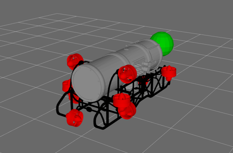
Fig 17. Image of simulator environment.
Acoustics Processing
The acoustics processing software was programmed using Code Composer Studio in the language of C++. After receiving a signal from the hydrophone array, unwanted frequency ranges are filtered out using a digital bandpass filter. The specified frequency range is 25-40 kHz.
Once the signal is received by Riptide’s three hydrophones, the angle of arrival of the emitted wave is calculated using phase difference between the three received signals. With the hydrophones positioned so that one whole wavelength is larger than their separation, the angle of arrival of the wave is calculated using the phase difference between each of the hydrophones and simple trigonometry. If the hydrophones were separated further than one wavelength then the phase difference could not be used since the system would not be able to determine which hydrophone received the signal first.
The heading information containing the direction that the vehicle needs to travel in order to reach the pinger is then sent to the central processing computer continuously until the breeching sequence activates.