Mechanical System
Primary Housing Module
The main housing is designed to provide easy access to the electronics for installation, maintenance, and diagnostics while minimizing disassembly. The vessel is made up of three main components, the central cylinder, and the forward and aft compartments. The central cylinder (Fig 4) secures the main housing to the chassis, and is not removed for regular maintenance. SubConn bulkhead connectors are able to pass through flat surfaces which were machined into the side of the housing. This allows for access to electrical components without disconnecting any connectors. To ensure the housing has the ability to be utilized in future years, a port on the underside of the central cylinder was machined to support a Doppler Velocity Logger.
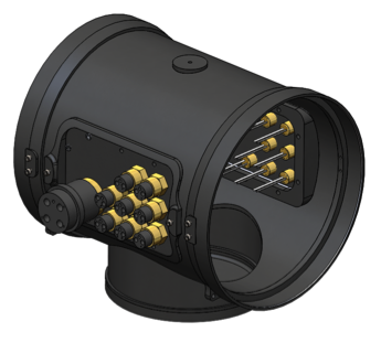
Fig 4. CAD rendering of central cylinder of primary module.
The forward and aft compartments are fully removable. The assembly is sealed on both sides by double x-profile radial O-rings and secured by locking stainless steel latches. This allows for quick disassembly without risking incorrect reassembly, which could result in a leak. The forward compartment is made of an acrylic tube to allow an observer clear view of the main electronics boards for diagnostic purposes, as well as a downward facing camera view. This housing can be easily expanded and re-used in the future if the electronics volume changes. Both compartments have clear acrylic end caps to support stereoscopic cameras and a diagnostic screen. A CAD rendering of the primary module can be seen in Fig 5.
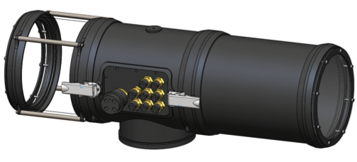
Fig 5. CAD rendering of primary module with latches engaged.
The main housing was entirely custom made for this vehicle. The sealing rings on the front and rear of the three main cylinders, the bulkhead connector inserts, and the DVL port were machined in-house on a CNC machine. The parts were welded to reduce the machining complexity, and then post-weld machining was completed to bring the parts to final dimension.
Auxiliary Housing Modules
The auxiliary external housings contain the batteries, pneumatic valves and switches, and acoustic sensors. These were designed to be able to be moved around on the vehicle during the final design phase to evenly balance the vehicle, reducing the need for additional ballast weight or buoyant material. The auxiliary housing locations on Riptide can be seen in Fig 6.
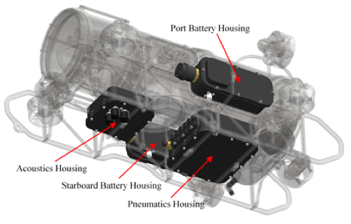
Fig 6. CAD rendering showing Riptide’s secondary modules.
The four housings have similar sealing methods that have been implemented and tested on previous vehicles. A lid is secured against a sealing flange using evenly spaced fasteners that are tightened to a specified torque, as shown in Fig 7. Housings that require a pass-through connection to the external environment were designed to have a reinforced bulkhead in the region that the connector will pass through. All structural features of the external housings were designed specifically for Riptide and were machined from raw aluminum alloy stock in-house using CNC and manual machining processes.
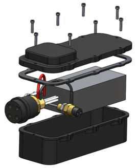
Fig 7. Exploded CAD rendering of battery housing.
To make Riptide start and stop a run, or stop in an emergency, an external switch was designed. Since there were no good options for a commercial watertight button, a housing was designed to hold the buttons. The base consists of a Delrin block with holes for the two buttons as well for the SubConn bulkhead connector. On top of the base is a series of gaskets and aluminum plates to hold the gasket and buttons in place, as shown in Fig 8. There is a momentary switch for starting and a maintained switch for the emergency shutoff. To ensure the kill switch can be pressed in an emergency an additional shaft and large button head was machined and placed on top of the design base.
Fig 8. Exploded CAD rendering of kill switch.
Chassis
The vehicle features a modular design that is based around a central chassis, shown in Fig 9. The chassis is made from water-jet aluminum sheets and joined with stainless steel fasteners. There are hard-points for securing the toolpackages and reinforced regions to handle the vehicle. The vehicle may be carried by handles on the front and rear or hung from a crane to allow easy deployment.
Fig 9. CAD rendering of Riptide’s chassis.
Pneumatics
The pneumatics system is controlled by eight 3-way electronic solenoid valves. The valves are part of a manifold to reduce the number of connections as well as make the system more space efficient. The pneumatics system is kept isolated in the pneumatics auxiliary housing located near the bottom of the vehicle.
Air is supplied by an onboard, externally mounted, air cylinder. The pressure is regulated down to the working pressure of 38 psi to allow a constant working pressure until the tank is nearly depleted. Air lines pass through a custom reinforced bulkhead that supports the use of off the shelf fittings.
Actuators
Riptide is able to move and complete the various tasks of the RoboSub competition through the use of several actuators mounted to the chassis of the vehicle.
Grippers
There are two manipulators on Riptide, located on either side of the vehicle along the forward housing compartment. The claws were designed to reach as far as possible while still maintaining a low profile when not in use. To do this, a two way linear actuator was used. The claw arms were waterjet and Delrin inserts were used around the screws to reduce friction during actuation. Additionally, stainless steel rods with a slider were used to reduce any side loading. A CAD rendering of one of the claws can be seen in Fig 10.
Fig 10. CAD rendering of Riptide’s claw.
Marker Droppers
There are two marker droppers aboard Riptide, located on either side underneath the central cylinder of the housing. Each marker dropper is operated by a permanent magnet, a steel 1 in diameter ball, and compressed air. The steel marker ball rests in a cylindrical chamber and is separated from the magnet by a 1/8” Delrin plate. The plate is thin enough that the magnet can keep the ball still, yet it is thick enough that firing compressed air through a check-valve at the top of the chamber can overcome the magnetic force and release the ball. Gaskets are used to water-tight seal the magnet. A gasket is placed between the magnet and the top plate and between the magnet and the magnet face plate.
Other designs were considered, but this design was ultimately chosen due to simplicity. Another design required pneumatic controls which would have worked, yet required additional hardware for the AUV. The final physical design was chosen based on machinability. Other previous designs were found to be too difficult to machine or too difficult to replicate more than once if something went wrong with the first part. The use of Delrin as the main component material kept the part lightweight, easy to machine, and inexpensive.
Torpedo Launchers
The torpedo launchers consist of two Delrin barrels held in place by two Delrin support structures, shown in Fig 11. The launchers are attached at the top of either side of Riptide’s forward housing compartment. Two torpedoes are launched from the barrels through the internal pressurization of the torpedoes themselves. At the pneumatic pressure’s peak, the torpedo slips passed the O-ring keeping it attached to the pneumatic valve and speeds forward through the water. The torpedoes consists of a 1.5-inch diameter head attached to a 0.75-inch diameter shaft that has 3 stability fins attached at its base. The 5-inch long torpedo fits snugly in the 5.5-inch long barrel to assure that all air pressure is devoted to pushing the torpedo out of the barrel and so the torpedo does not wobble prior to exit.
Fig 11. CAD rendering of Riptide’s torpedo launcher system, with one torpedo in resting position and one in the launched position.
The initial stages of the torpedo launcher’s development began with extensive research into approaches of past successful teams. It was found that pneumatics seemed to be the most feasible option for success.
After finalizing the pursuance of a pneumatic launcher system, the next step was to determine how to pressurize the mechanism. Several methods were proposed including pressurizing the barrel external to the torpedo. Finally, the decision was made to pressurize the inside of the torpedo itself to eliminate the friction vs. effective sealing decision of the torpedo-barrel contact.
Most of the machining was done on a lathe including the barrels (turned and bored), the torpedo head (turned and bored), and the torpedo shaft (faced). The support structures for the barrels were water-jet by a third party.
Thrusters
Ten T200 thrusters from Blue Robotics are utilized on Riptide and give it the ability to move with six degrees of freedom. The thrusters are fixed to the water-jet chassis, four horizontal, four vertical, and two sideways. The thruster wires were cut to length, soldered, and resin was injected in molds to seal the electrical connections.