Electrical System
Onboard Computer
The computer onboard Riptide for running all software packages and sensors consists of a BCM Advanced Research MX87QD motherboard with an Intel Core i7-4790S CPU.
Sensors
The sensor suite that is utilized on Riptide consists of two inertial measurement units (IMU), one LORD MicroStrain 3DM-GX4-25 and one 9-DOF RAZOR IMU, for acceleration and orientation information, three Point Grey Blackfly USB3 Vision cameras (BFLY-U3-13S2C-CS) for vision processing and visual odometry, one Blue Robotics Bar30 pressure sensor for measuring the depth of the vehicle, and three Aquarian Audio H1C hydrophones for acoustic signal processing.
Internal Electronics
Backplane
The backplane is a circular printed circuit board with 11 female connectors. All of the boards in the inside housing mount to this board, creating a wireless system for all the boards to communicate and source power from one another, as shown in Fig 12.
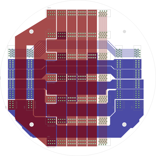
Fig 12. Board layout of backplane.
The power system is mounted on the four edge connectors from either side, while the thruster controller board and five electronic speed controller (ESC) boards are mounted down the center, as the ESC boards must receive signals from the master thruster board. Five and twelve volts are converted from the balanced load sourced from the power distribution board and then distributed to each board through the designated pins. However, the boards may communicate only within their system; e.g. the thruster controller board may only talk to the ESC boards, but not the 12 V board. By separating the communication signals, the amount of noise is reduced. Finally, the backplane has four holes in each corner. This is where the board is mounted in the main housing. An image of the assembled electronics mounted on the backplane can be seen in Fig 13.
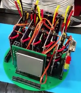
Fig 13. Custom Electrical Assembly.
Power Distribution
The power distribution board manages the load from both batteries and communicates the status of all the power system boards to the computer. First, both currents travel through a 30 amp fuse to prevent an overcurrent in the system. Current sensors individually monitor both batteries, and then the current paths are merged using a low-loss power path controller. The balanced voltage then enters the edge connector. This board has two RS-232 connections, as well as three small Molex connectors. Because there is a large current flow through this board, there are several decoupling capacitors around the microcontroller to remove noise. The board layout for the power distribution board can be seen in Fig 14.
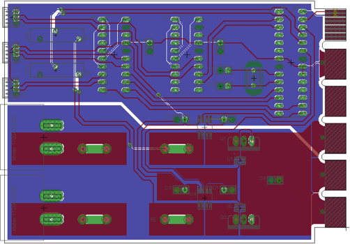
Fig 14. Board layout of power distribution board.
Power Conversion
Power conversion is completed with a 12 V and a 5 V board. The purpose of the 5 V converter board is to take the raw voltage from both batteries and alter the 18.5 V to the desired 5 V. First, the raw voltage flows from the power distribution board to the edge connector. This then follows large traces to a Murata isolated 5 V DC-DC board. The newly converted voltage is then fed into a current sensor, so that the team may monitor the flow of power and potentially cut power from the robot if there is significant overcurrent. After the current has been measured, the 5 V is then sourced into a specified pin on the edge connector, which all other boards use to obtain 5 V. This board also has board-to-wire connectors for fans that will help circulate air throughout the main housing.
The 12 V converter board simply converts the raw 18.5 V into 12 V in a similar process to the 5 V converter board. However, this board features a trim pot that is connected to the sense pins in order to adjust the output voltage. Again, the output of the 12 V converter board is fed into a current sensor to monitor if the current flow is correct and stable, and then flows into the designated 12 V pin. All other boards will source from this pin for 12 V if needed. This board directly powers the computer to ensure that there are no significant drops in current in order to prevent the system from rebooting
Thruster Controller
The thruster control board relays commands between the computer and the individual motor ESC boards, as well as monitoring the status of each ESC and the state of the kill switch. An atmega328 microcontroller communicates with the computer via a RS-232 serial signal. The computer sends the power level for each thruster through this connection then the microcontroller relays these power levels over an I2C port to the ESC boards. Through the same I2C connection each ESC board returns current and controller temperature data. The kill switch is connected through this board, allowing it to activate the thrusters.
ESC Controllers
The ESC board is designed to send a PWM signal to each motor controller, as well as monitoring the status of each thruster and controller. Each individual board has two motor controllers. The battery power comes in from the backplane. The power then goes through two relays that are hardwirecontrolled by the kill switch. The relays are fail open, or in other words the kill switch has to be providing 5 V to each relay in order for the thrusters to be powered. There are four sensors on each ESC board: a current sensor and temperature sensor for each motor controller. An attiny1634 microcontroller communicates with the thruster control board over an I2C bus, receiving the desired thrust level and sending the sensor data for each thruster. An image of a complete ESC board can be seen in Fig 15.
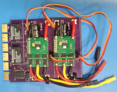
Fig 15. ESC circuit board.
External Electronics
Within the secondary modules of Riptide there are several electrical systems in place to provide power to the vehicle and to control several external devices.
Battery Monitoring
Riptide is powered by two MaxAmps 8000 mAh 18.5 V Dual Core battery packs, allowing for two to three hours of testing depending on intensity.
There are battery monitor boards located in each battery housing. They monitor the temperature and pressure within the housing to ensure the battery conditions are safe and allow efficient operation. This status data is relayed to the Power Distribution board over a RS-232 serial connection.
Pneumatics Controller
The Pneumatic control board activates the solenoid valves that direct air to the pneumatic actuators on the AUV. An atmega328 microcontroller receives commands from the computer through an RS-232 to UART interface to control eight separate outputs. Darlington transistors are used to amplify the logic signal to a higher current, 12 volt signal used to drive the solenoid valves.
Acoustics Processing
Three hydrophones mounted below the vehicle provide data for determining the pinger’s position. The hydrophones are separated such that the underwater pinger’s transmitting wave cannot travel one whole wavelength in between the hydrophones.
The acoustics processing is currently being completed with a Codec shield connected to an Arduino Uno. The shield has a WM8731S Codec for capturing the hydrophone data, which is then transferred to the main computer for processing.
Backplane Assembly
First, connect all boards to the backplane via edge connectors. The five and twelve volt DC/DC converters should be on opposite sides; with the twelve volt board on the opposite side of the power distribution board. The power distribution board is plugged into the outermost (left) side of the backplane, where the two battery connectors come through the main housing. Finally, the thruster controller board is plugged into the bottom (horizontal) edge connectors, with all five of the thruster controller boards plugged in overtop.
A quick summary is as follows: the middle column of the backplane only has horizontal edge connector slots. There is one extra slot in this column. From top to bottom, there should be [empty: ESC: ESC: ESC: ESC: ESC: THRUSTERCTRL]. From left to right, with card edges facing out, the order should be [PDB: 5V: EMPTY: 12V].
When all boards are mounted to the backplane, the backplane may now be mounted into the vehicle. The two longer rubber mounts slide on the mounting rods of the main electronic housing. Then, the 10 ESC’s must naturally be connected to the thrusters. Red goes to red, yellow goes to yellow, black goes to black. Currently, we have no steadfast way (10/16/2016) to delineate which set of cables are connected to each ESC, as well as which order the ESC Boards are connected in, due to repetitive failure of relays. This is the first order of business in the new board set up.
The kill switch plugs into the small, white Molex connector on the Thruster Controller Board; the ON-OFF switch plugs into the same model connector on the Power Distribution Board. There is a square, four pronged connector that connects the mother board to the 12 V DC/DC Converter. Finally, the two batteries plug into the Power Distribution Board using Molex Super Sabre connectors.
Pneumatics Electronics Assembly
The pneumatics electronics were set into the electronics mounting frame and screwed in.
Battery Board Assembly
The battery boards were mounted by a screw in each corner of the board. These screws went into delrin stakes that lifted it above the wiring of the batteries.