Assembly & Mounting
Guidelines
Fasteners
Use antiseize if aluminum is used in the mate. Look up max tightening torque for bolt size and materials mating.
LOCTITE 222 THREADLOCKER is applied to all bolts/screws threading into stainless steel or connecting the sealing latches to the main aluminum housing. MARINE GRADE ANTI-SEIZE is applied to all other bolts/screws threading into aluminum prior to fastening. 8-32 bolts used to compress gasket should be tightened to a torque of 9 inch-pounds. All other bolts/screws should be hand-tightened.
Warning
The heads of all bolts/screws must be free of wear and show no indication of stripping (damaged fasteners should be discarded immediately).
Gaskets
The rubber is free of cuts and scratches that cross the entire surface. All holes for bolts hold the fastener snuggly. When compressed, the gasket is extruded evenly around all sides.
O-Rings
The rubber is free of all nicks, cuts, excessive wear, discoloration, and/or permanent deformation. The o-ring groove is free of water and solid particles. The o-ring has been greased with MOLYKOTE 55 o-ring grease prior to every fitting.
Star Pattern
Do it twice. Then, starting at the 12 o’clock position and working clockwise, tighten each bolt.
Anti-Seize
Roll the last quarter inch of the bolt in anti-seize making sure to thoroughly coat all threads. Wipe the excess off such that the remaining anti-seize completely fills the space between threads. (Roll threads of coated bolt around threads of uncoated bolt to transfer excess anti-seize and ensure threads are fully coated.)
Chassis
Fasteners
Use only SS 18-8 #8-32 3/4” bolts to tighten components together with antiseize.
| Part | Hex Driver Size |
|---|---|
| Chassis | 9/64” |
| Thrusters | M2.5 |
| Marker Dropper | 3/32” |
Thrusters
Removal
- Remove subconn from subconn plate. Note: use colour method to keep track of thruster
- 3-32 hex key to unscrew 4 bolts connecting thruster to chassis
The thrusters have been taped in colored bands.
The taped bands can be read as follows:
Band #1
| Red | Yellow | Blue |
|---|---|---|
| Surge | Heave | Sway |
Band #2
| Green | White |
|---|---|
| Forward | Aft |
| Top | Bottom |
Band #3
| Green | White |
|---|---|
| Port | Starboard |
Electronics Housing
Fasteners
add metric conversion
| Mating | Count | Material | Thread | Length | Torque | Coating |
|---|---|---|---|---|---|---|
| Forward Endcap | 8 | Nylon | 8-32 | 0.875in | 9in-lbs | Anti-Seize |
| Tension Rods | 8 | Krylon | 8-32 | 0.5in | Hand-tight | LOCTITE |
| Aft Endcap | 8 | Nylon | 8-32 | 1.0in | 9in-lbs | Anti-Seize |
| DVL Tube Cap | 6 | Krylon | 8-32 | 0.875in | 9in-lbs | Anti-Seize |
| Port I/O Panel | 10 | Nylon | 8-32 | 1.0in | 9in-lbs | Anti-Seize |
| Starboard I/O Panel | 10 | Krylon | 8-32 | 1.0in | 9in-lbs | Anti-Seize |
| Extension Latches | 12 | Nylon |
Seals
| Mating | Count | Method | Size | Coating |
|---|---|---|---|---|
| Pressure | 1 | Twist? | ||
| Clear Tube | 2 | Gasket | None | |
| Mid Housing | 4 | X-Ring | O-Ring Grease | |
| DVL Tube Cap | 1 | Gasket | None | |
| I/O Panels | 2 | Gasket | None |
- Black Gaskets: Buna N 1/16” Thick (Formed from o-ring material.)
- See Exterior Cables & Hoses for SubConn connections.
Assembly
Warning
Ensure all fasteners attaching latches are tight and the sealing gasket appears compressed. DO NOT OVER TIGHTEN IF SECURED!
Central Core:
- Place the DVL Tube Cap gasket on the tube.
- Place the DVL cap on the DVL Tube Cap gasket.
- Secure the DVL cap using 6 DVL Tube Cap fasteners.
- Line up the ‘ff’ label on DVL with ‘ff’ label on housing for buoyancy.
Note
For the time being the outermost rear fan bolts must be removed to insert and remove the electronics rocket.
- Secure the pressure sensor wire out to the upper surface of the housing to prevent it from catch on the electronics rocket.
- Insert (Land) electronics rocket from the forward side of the tube.
- PUT THE O-RING ON THE PANEL THEN PUT THE SCREWS IN AND THEN PUT IT ON.
- Place an I/O Panel gasket into the port mid housing receptacle. (Add link to panel chart.)
- Place the Port I/O panel against the I/O panel gasket with the giant power SubConn on the forward side.
Warning
Using a flashlight inspect the interior mating face to ensure the gasket is properly seated, repeat with finger.
- Secure the Port I/O panel using 10 Port I/O Panel bolts by first applying anti-seize then finger-tightening them and then preceding to do the star stuff. (Add links.)
Warning
Ensure the I/O panel bolts pass through the electronics rocket without being forced, or they’ll bend it and warp it.
REPEAT THE PORT PROCEDURE WITH THE STARBOARD SIDE...
- Place the Starboard I/O Panel gasket into the starboard mid housing receptacle.
- Place the starboard I/O panel atop the I/O panel gasket.
- Secure the starboard I/O panel using [some fasteners].
Backplane:
- Add screws! Four, 4-40, 3/8”, hand-tight, stainless
- Bolt the backplane to the electronics rocket’s four canty-lever rods using backplane screws and washers.
- Connect all the cables.
After Extension:
Attaching the lid:
- Clean the mating surfaces and gasket, ensuring to remove any excess anti-seize.
- Place the gasket onto the housing mating surface and then place the lid onto the gasket.
- For each of the 8 lid bolts, apply anti-seize and then insert the bolt about 3/4 of the way.
- Tighten all bolts using the star pattern procedure.
Preparing the o-rings:
- Clean out the o-ring housing grooves with cotton swabs, wash your hands or don gloves.
- With clean hands squeeze a “pea and a schmear” sized amount of o-ring grease onto your thumb and forefinger.
- Pull the o-ring through the grease while applying steady pressure to ensure the o-ring is evenly coated. (Perform 3 revolutions of the o-ring to ensure an even coating.)
- Starting with the o-ring in contact with the aftermost groove, stretch the o-ring around the circumference of the tube and release it into it’s slot.
Warning
Check the o-ring to make sure it is not twisted.
- Repeat for the second o-ring.
Inserting the tube:
- Align the housing with the vehicle so that the latch tabs are horizontal.
- Place the leading edge of the housing onto the after frame curved crossbar.
- While being careful to avoid contact with the backplane, slide the housing forward until, it is within an inch of the central portion.
- Slide the mating surfaces together, pushing firmly to engage the first o-ring.
- Hook the latches over the latch tabs, and close them until the locks catch. Pull back to ensure successful locking mechanism engagement.
- The housing is sealed if and only if both mating surfaces are now in full contact with one-another. (The upper portion will be more “in full contact” than the lower portion.)
Forward Extension:
Attaching the lid:
- Clean the mating surfaces and gasket, being careful to remove excess anti-seize.
- Place the gasket onto the housing mating surface and then place the lid onto the gasket.
- For each of the 8 lid bolts, apply anti-seize and then insert the bolt about 3/4 of the way.
- Tighten all bolts using the star pattern procedure.
Preparing the o-rings:
- Clean out the o-ring grooves with cotton swabs, wash your hands or don gloves.
- With clean hands squeeze a “pea and a schmear” sized amount of o-ring grease onto your thumb and forefinger.
- Pull the o-ring through the grease while applying steady pressure to ensure the o-ring is evenly coated.
- Starting with the o-ring in contact with a groove stretch the first o-ring around the circumference of the tube and release it into it’s slot.
Warning
Check the o-ring to make sure it is not twisted.
- Repeat for the second o-ring.
Inserting the tube:
- Align the housing so that the latch tabs are horizontal.
- Place the leading edge of the housing onto the forward frame curved crossbar.
- Tilt the housing forward until the lower leading edge is low enough to pass below the downward-facing camera.
- Push the housing longitudinally for an inch before leveling the housing.
- While being careful to avoid contact with the camera, slide the housing aft until, it is within an inch of the central portion.
- Slide the mating surfaces together, pushing firmly to engage the first o-ring.
- Hook the latches over the latch tabs, and close them until the locks catch. Pull back to ensure successful locking mechanism engagement.
- The housing is sealed if and only if both mating surfaces are now in full contact with oneanother.
Acoustics Housing
Fasteners
| Mating | Count | Material | Thread | Length | Torque | Coating |
|---|---|---|---|---|---|---|
| Mounting Block | 3 | Krylon | 8-32 | 0.5in | 9in-lbs | Anti-Seize |
| Housing Lid | 8 | Nylon | 8-32 | 0.75in | 9in-lbs | Anti-Seize |
Seals
| Mating | Count | Method | Size | Coating |
|---|---|---|---|---|
| Hydrophone Block | 1 | Gasket | None | |
| Housing Lid | 1 | Gasket | None | |
| Hydrophones | 3 | Screw? |
- See Exterior Cables & Hoses for SubConn connections.
Assembly
- Securely tighten hydrophones to mounting block.
- Place hydrophone gasket on [something].
- Place hydrophone block on hydrophone gasket.
- Secure block and gasket using three mounting block fasteners.
- Place lid gasket on housing.
- Place lid on gasket.
- Secure lid and gasket using eight lid fasteners in a star pattern.
Battery Housings
Note
The following applies to a single battery housing and must be repeated for the second housing.
Fasteners
| Mating | Count | Material | Thread | Length | Torque | Coating |
|---|---|---|---|---|---|---|
| Relief Valve | 4 | Krylon | 8-32 | 0.5in | 9in-lbs | Anti-Seize |
| Housing Lid | 8 | Nylon | 8-32 | 0.75in | 9in-lbs | Anti-Seize |
Seals
| Mating | Count | Method | Size | Coating |
|---|---|---|---|---|
| Relief Valve | 1 | |||
| Valve Block | 1 | Gasket | None | |
| Housing Lid | 1 | Gasket | None |
- See Exterior Cables & Hoses for SubConn connections.
Assembly
- The relief valve has to go on to the mounting block FIRST.
- Screw NPT thread valve onto mounting block.
- Secure the valve assembly to the housing using 4 relief valve bolts.
- Place the housing lid gasket on the housing.
- Place the lid gasket onto the housing.
- Place the lid onto the housing and gasket.
- Secure the lid using 8 fasteners in a star pattern.
Mounting
Note
The data SubConn must be attached to the battery housing and all other main housing subconns must be attached prior to placing the battery housing into it’s receptacle.
- Align the battery housing such that the power cable is facing forward and the data cable is facing upward (relief valve down).
- Place the battery housing into the chassis receptacle by first inserting the aft end working the forward portion in.
- Secure the battery housing by closing the retaining arms and engaging the latch.
- Repeat for the other side.
Pneumatics Housing
Warning
If the pneumatics system will not be used and the hoses will not be inserted the grabbers and pnuematics housing must be removed from the vehicle prior to submerging.
Fasteners
| Mating | Count | Material | Thread | Length | Torque | Coating |
|---|---|---|---|---|---|---|
| Relief Valve | 4 | Krylon | 8-32 | 0.5in | 9in-lbs | Anti-Seize |
| Tube Matrix | 6 | Nylon | 8-32 | 0.75in | 9in-lbs | Anti-Seize |
| Housing Lid | 12 | Krylon | 8-32 | 0.75in | 9in-lbs | Anti-Seize |
Seals
| Mating | Count | Method | Size | Coating |
|---|---|---|---|---|
| Relief Valve | 7 | Gasket | None | |
| Tube Matrix | 1 | Gasket | None | |
| Housing Lid | 4 | Gasket | None |
- See Exterior Cables & Hoses for SubConn connections.
Pneumatic Connections:
- All ports on external pneumatics matrix occupied and secured
- Ports on internal pneumatics matrix occupied if necessary and secured
- pneumatic arrangement:
Assembly
Warning
The housing lid and gasket appear to be a square, but are in fact rectangular. Take special care to align the lid and gasket properly or
- Put the relief valve itself onto something.
- Place relief valve gaskets where they go.
- Put the relief valve block between them?
- Secure the relief valve using four Krylon bolts.
- Place tube matrix gasket on the housing.
- Place tube matrix on the gasket.
- Secure the tube matrix and gasket using 6 Nylon bolts.
- Place the housing lid gasket on the housing.
- Place the housing lid on the gasket.
- Secure the housing lid and gasket using 12 screws.
Mounting
- 4 Latches must secure pneumatics housing to chassis
- Bolt housing to chassis with 9/64” hex driver
- For removal, keep 2 forward latches secured while unscrewing bolts
Removal of Air Tank
- Remove hose from nozzle of tank. Close valve securely!
- Hold tank and remove 4 screws holding paintball tank to chassis using 4-40 hex key. Note: pull tank towards screws, thruster removal NOT neccessary
- Slowly remove tank: Twist tank so delrin mounting points are upward and remove tank.
Main Housing
Warning
Careful not to twist or tear O-rings during assembly Visually check the mating interfaces have a uniform gap
Front Cap Assembly
.# Place the front cap bottom stainless steel rods in the channels. .# Line up the sealing surfaces. .# Engage latches by carefully forcing front cap into main housing. .# Pull latches at the same time to fully close the front of the vehicle.
Back Cap Assembly
.# Attach the Acrylic plate to rear end of the Aluminum tube. .# Place the #8 screws on the aluminum ring through the acrylic plate. .# Place the gasket on all the screws. .# Torque screws to 9 in-lb in a star pattern. .# Lube 2 X-profile Bruna-N 265 O-Rings and place in O-Ring grooves. .# Slide the back cap around the backplane. .# Line up the sealing surfaces. .# Engage latches by carefully forcing front cap into main housing. .# Pull latches at the same time to fully close the front of the vehicle.
Disassembly
- Unlatch latches on side needed.
- Firmly Pull each tube out. Do NOT damage O-ring seals.
- Remove Subconn plates and clear interior electronics. Note: careful of red pressure sensor cord. See interior electronics removal.
- Unscrew 4 bolts that attach housing to chassis using 9-64 hex key.
- Lift main housing straight up.
Manipulator
Assembly
.# Check the Pneumatic connections by grabbing the black tubing and giving a gentle push towards the fitting .# Remove the Velcro straps before use. .# See control matrix table on the actuation of the Pneumatic piston
Control matrix:
| A | B | Effect |
|---|---|---|
| on | on | lock |
| on | off | fwd/rev |
| off | on | rev/fwd |
| off | off | relax |
Marker Droppers
Assembly
.# Place the marker chamber on a flat surface, open end down. .# Place the magnet chamber base on top of the marker chamber. .# Slip cylindrical magnet over the magnet chamber base. .# Place the magnet chamber barrel on the chamber base. .# Place the magnet chamber top on the magnet chamber barrel. .# Fasten the assembly with three countersunk #4-40 1” bolts. .# Tighten bolts to 45 oz-in. .# Attach a push-to-connect one-way valve to the top of the magnet chamber. .# Place market in marker chamber. .# Attach assembly to the chassis underside of the vehicle with two #4-40 1” bolts. .# Hand-tightened .# Connect Pneumatic hose to the push-to-connect one-way valve. .# To operate, actuate solenoid to release pressurized air and drop marker
Torpedo Launchers
Assembly
torpedo barrel x 2: .# Apply #014 O-ring to the O-ring groove on the shaft of the end-cap. .# Insert the end-cap onto the barrel and secure with one countersunk#4-40 bolt 1/2”. .# Attach the push-to-connect one-way valve to the small hole in the end-cap and secure with Teflon tape. .# Put each of the barrel mount’s holes over either end of the barrel. .# Attach the Barrel-Barrel Mount assemble to top side of the front chamber of the vehicle. .# Attach pneumatic hose to push-to-connect one-way air valve. .# Push torpedo into barrel until the torpedo shaft slides over the O-ring on the end-cap.
Operation: Actuate solenoid to release pressurized air and fire torpedo.
Exterior Cables & Hoses
Warning
The bulkhead connectors are tightened against mounting surfaces. MOLYKOTE 44 MEDIUM grease is applied to all male pins before mating.
You can download this cabling diagram or this block diagram.
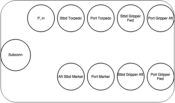
Main Housing I/O Panel – Port
Note
All SubConns have strain reliefs with the exception of bottom port surge.
| Connection | Series | # Pins | Amps/Connector |
|---|---|---|---|
| Acoustics Housing | Micro Circular | 4 | 20 |
| Kill Switch | Micro Circular | 4 | 20 |
| Battery Housing – Port | Micro Circular | 4 | 20 |
| Battery Housing – Port | Power | 4 | 50 |
| Pneumatics Housing | Micro Circular | 4 | 20 |
| Thruster – Upper Surge | Micro Circular | 3 | 20 |
| Thruster – Lower Surge | Micro Circular | 3 | 20 |
| Thruster – Forward Heave | Micro Circular | 3 | 20 |
| Thruster – After Heave | Micro Circular | 3 | 20 |
| Thruster – Forward Sway | Micro Circular | 3 | 20 |
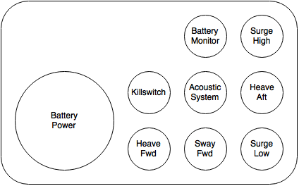
Main Housing I/O Panel – Starboard

Note
All SubConns have strain reliefs with the exception of bottom starboard surge.
| Connection | Series | # Pins | Amps/Connector |
|---|---|---|---|
| Pneumatics Housing | Micro Circular | 4 | 20 |
| Battery Housing – Stbd | Micro Circular | 4 | 20 |
| Battery Housing – Stbd | Power | 4 | 50 |
| Thruster – Upper Surge | Micro Circular | 3 | 20 |
| Thruster – Lower Surge | Micro Circular | 3 | 20 |
| Thruster – Forward Heave | Micro Circular | 3 | 20 |
| Thruster – After Heave | Micro Circular | 3 | 20 |
| Thruster – Aft Sway | Micro Circular | 3 | 20 |
| Tether | Ethernet | 8 |
Pneumatics Housing (Hoses)
| Connection | Color | Diameter |
|---|---|---|
| Supply | ||
| Manipulator – Port | ||
| Manipulator – Stbd | ||
| Marker Dropper – Port | ||
| Marker Dropper – Stbd | ||
| Torpedo Launcher – Port | ||
| Torpedo Launcher – Stbd |